Quasi-Square wave converter, an easily controlled soft-switching topology
Today I want to introduce a pwm-controlled soft-switching topology. It is called Quasi-Square-Wave converter. It has some benefits that interest engineers a lot; It is easily controlled just like traditional pwm converter, it has zero-voltage switching at turned-on transition and it inherently has a negative feedback mechanism to achieve current-sharing on paralleled application so there is no necessity having an active current sharing circuitry on this topology.
I did a simulation to illustrate how easy it can be to build a QSW-ZVS synchronous buck converter as below. And it is compared with the hard-switching synchronous buck topology.
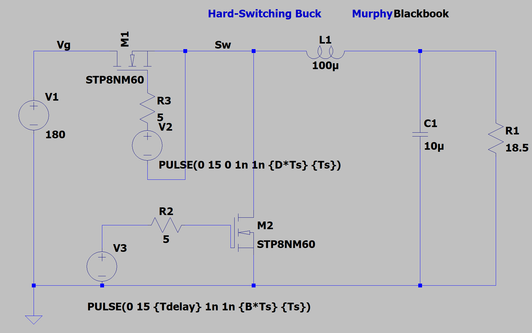
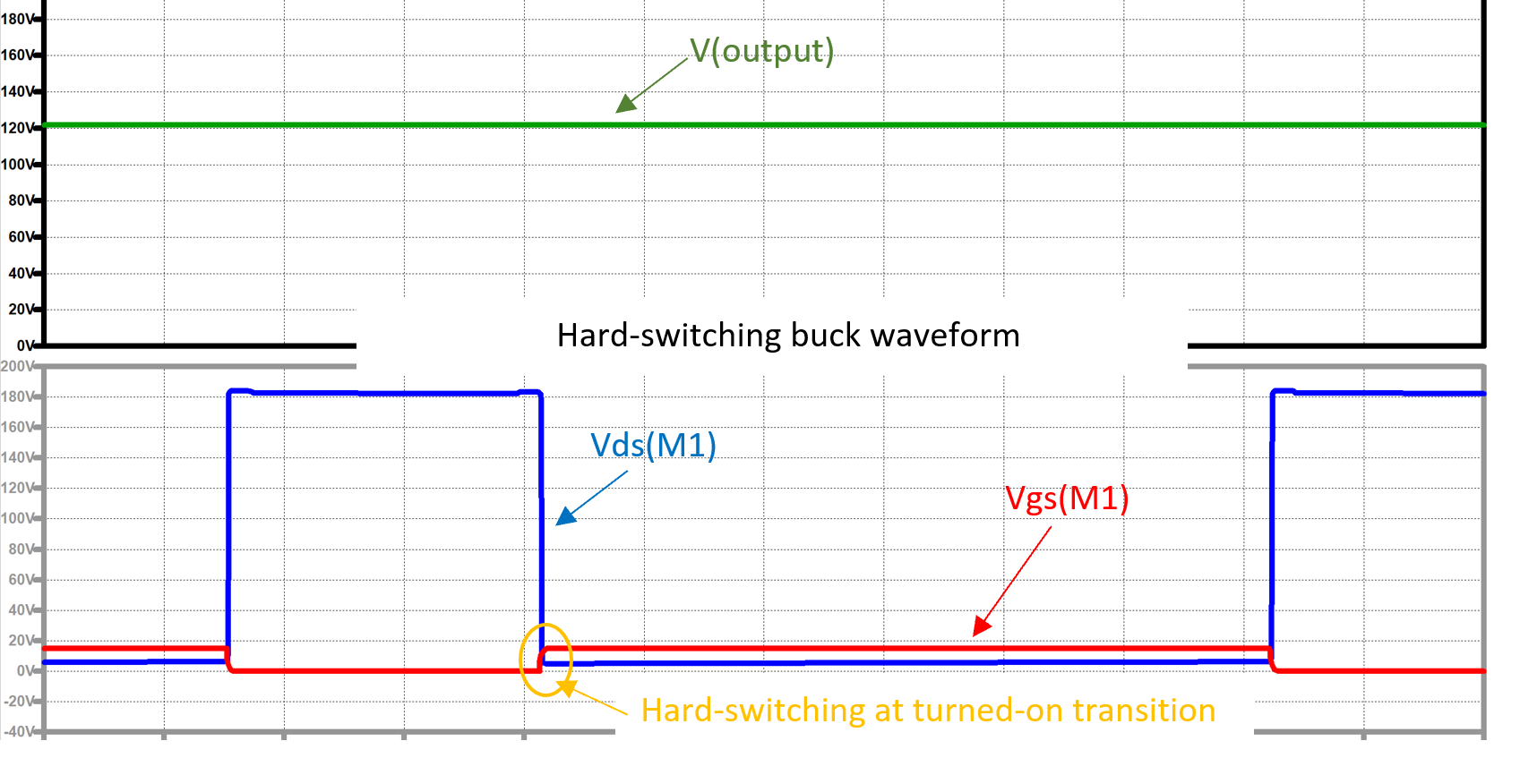
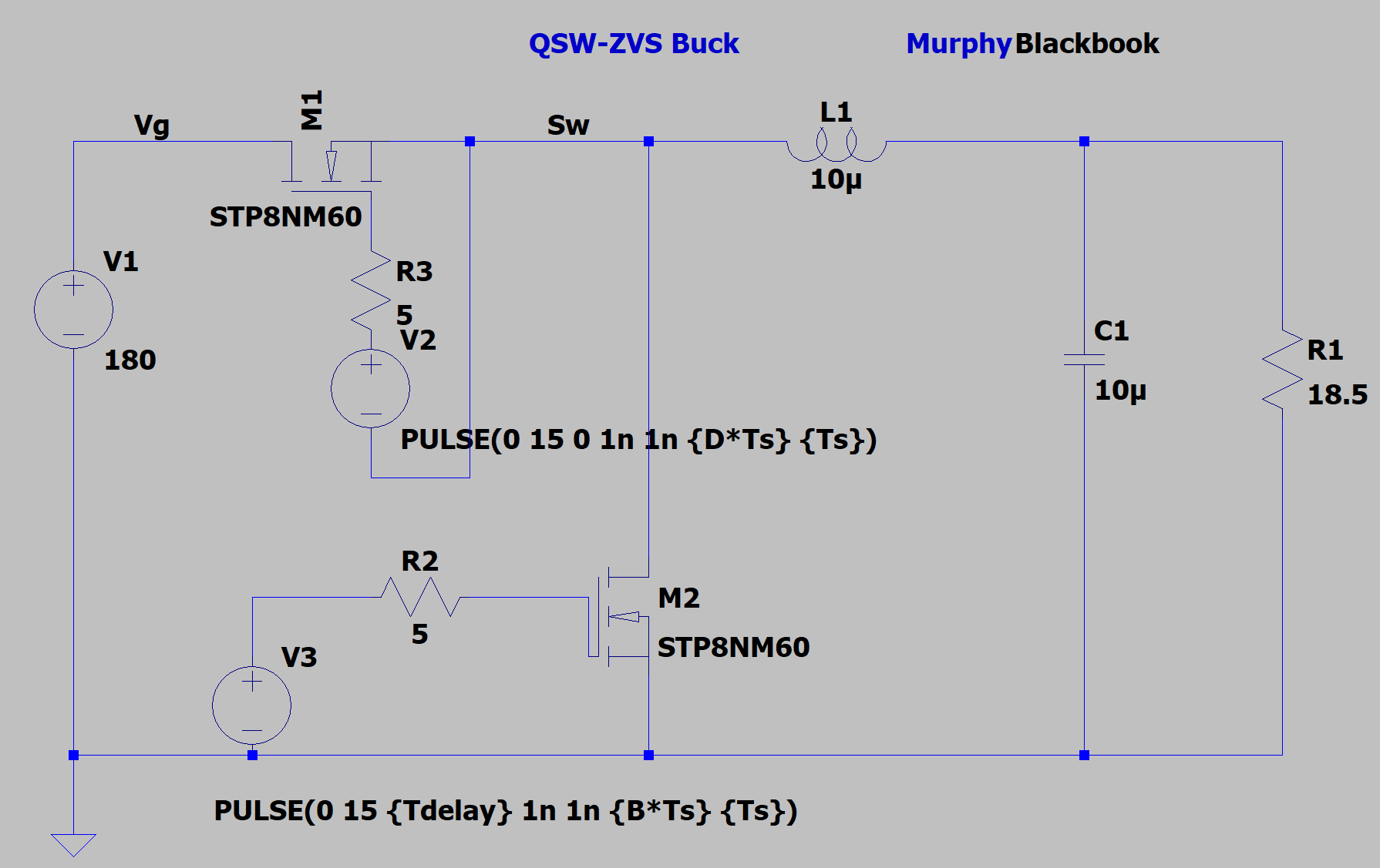
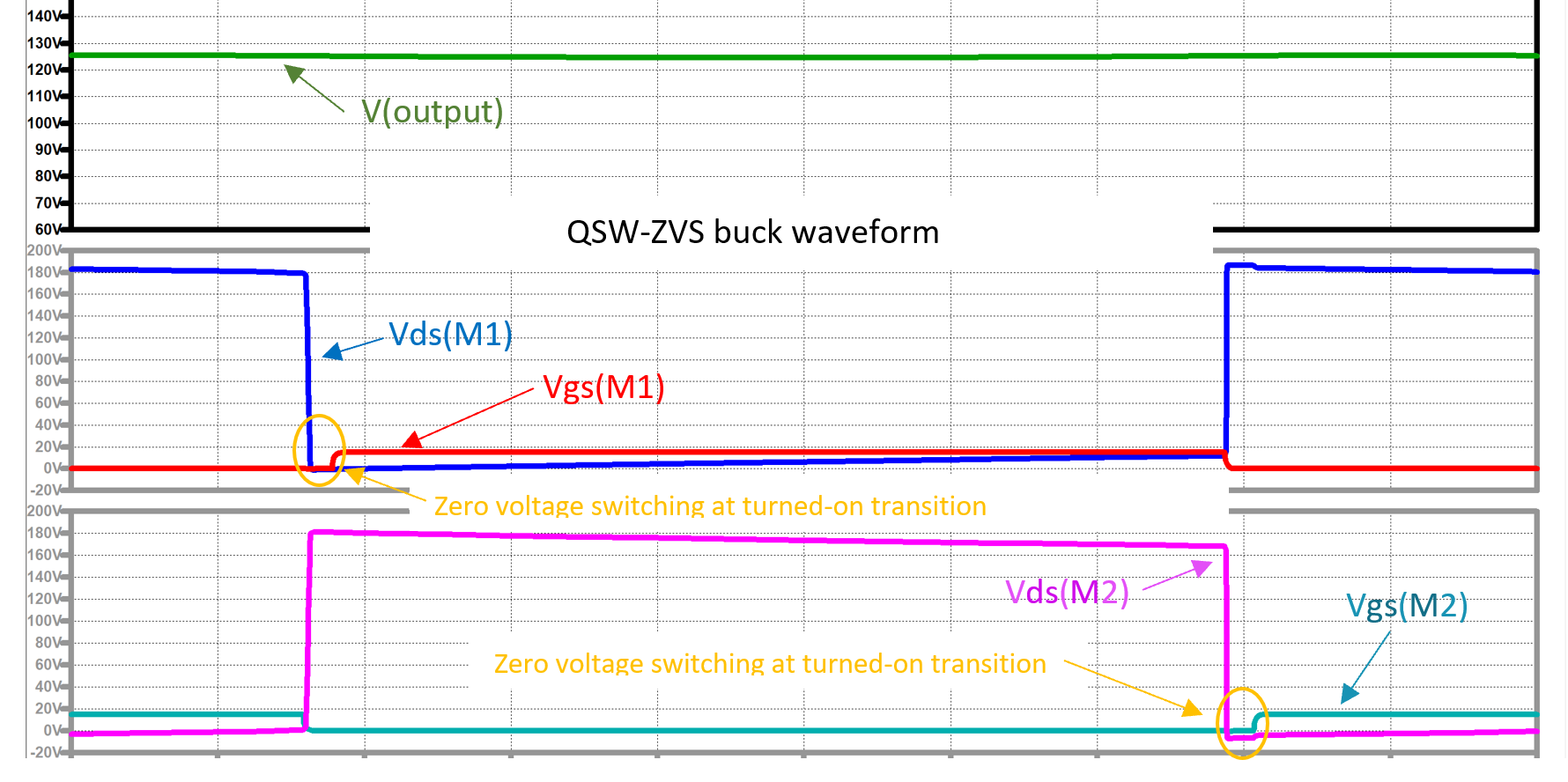
Have you figured out the difference I made to the power stage? I changed nothing but the inductance from 100uH to 10uH. This modification increases the peak current but makes soft-switching feature readily available. Nothing comes for free, as QSW-ZVS buck eliminates most of the switching loss, yet increases the conduction loss, because the reduction of inductance leads to larger current ripple. So, the calculation and selection of proper inductance is significantly important, and state-plane analysis would give you a physical insight on how it works.
Features of QSW topology:
1. 1.Tank capacitor is effectively in parallel with all semiconductor elements. All devices operate with zero-voltage switching.
2. 2.The peak voltage applied to all semiconductor devices is identical to the peak voltage in the (ideal) parent dc-dc converter. This resonant switch does not increase the voltage stresses on the components.
3. 3.Magnetics are small, and similar to magnetics of DCM converters.
4. 4.Voltage waveforms resemble those of hard-switched pwm converters except that the switching transitions are resonant and smooth.
5. 5.It is duty cycle-controlled in synchronous topology just like the traditional converters, simple and easy to control.
This approach finds significant commercial application in supplying low-voltage high-current microprocessors. Switching frequencies of several Mhz are not unusual.
If you are interested in what I share, I highly recommend you to watch this seminar held at UC Berkeley, and professor Dragan Maksimovic gave this presentation. He and His former PhD student did this project, a 100Mhz envelope tracking GaN power supply for 4G Cell phone base stations.
https://www.youtube.com/watch?v=jhz4EN3S4Zw&t=1s
Dragan Maksimovic, Charles V. Schelke Endowed Professor at University of Colorado at Boulder and Director of the Colorado Power Electronics Center (CoPEC), speaks at the Power Electronics Seminar on February 1, 2016 hosted by the Cal PELS Student Chapter.
If you like what I share, please give me a thumbs-up, it'll help me a lot. If you have any question, just comment below. If you want my simulation file, just contact me at 466288351@qq.com
Login
Enter your email address and password
© COOWA © 2018 Copyright