Brief Introduction of PLL (Phase-Locked Loop)
Date:2019-04-22 23:25:30 Posted by:Arthur View:500Applications: frequency division, frequency multiplication, demodulation for phase modulated signal, frequency synchronization, frequency synthesis and clock recovery.
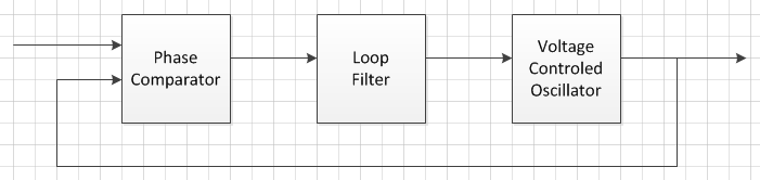
Basic structure diagram:
Explanations:
PLL is a closed loop feedback controlled system. The control target is to make the output frequency equal to (or a multiple of if optional divider is available) the given frequency and make their phase error least.
The phase comparator compares the feedback signal to the given signal, and gives the phase error between these two inputs.
The loop filter is a low pass filter, which produce a voltage involved with the phase error to control the VCO. And the negative feedback loop makes the phase error be least.
Voltage Controlled Oscillator (VCO) is an oscillator which produce a signal, and its frequency is controlled by the input voltage, and the phase is continuous when frequency varies.
The feedback path is from the output to one of the input of the phase comparator. A divider is optional.
PLL is widely used in digital circuits. For instance, MCUs and FPGAs to get the higher main clock by multiplying the lower crystal oscillator output. This makes lower cost, better EMI performance.


Login
Enter your email address and password
© COOWA © 2018 Copyright